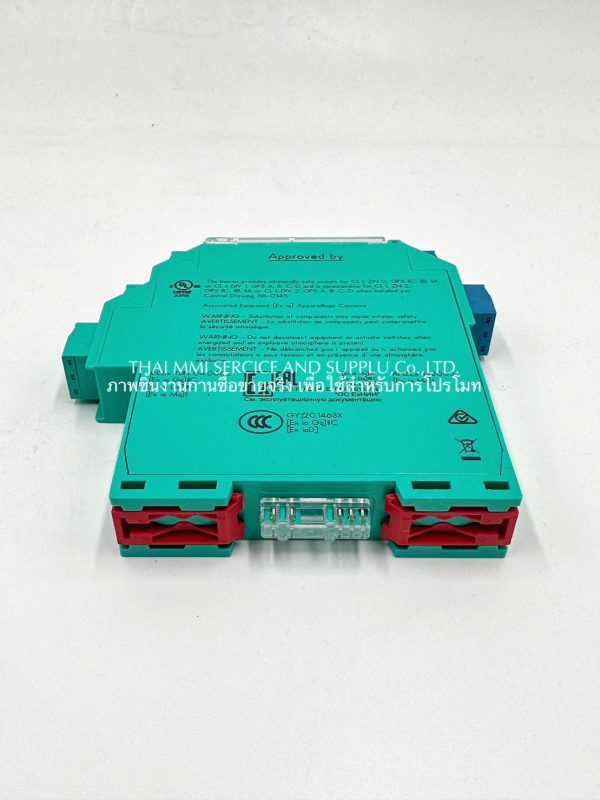
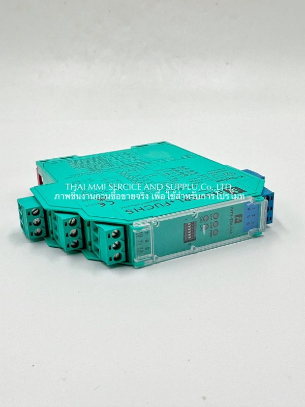
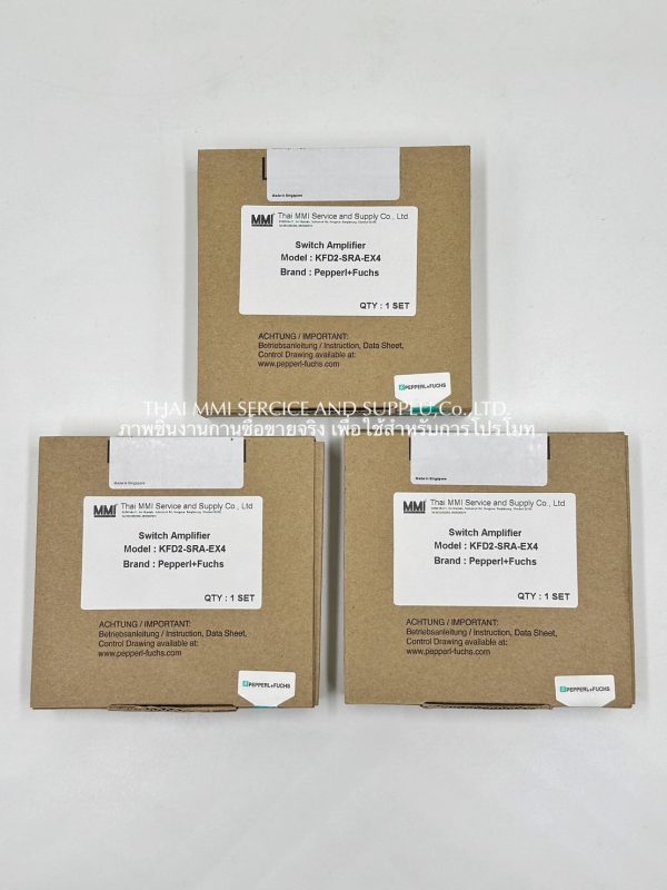


Pepperl+Fuchs : Switch Amplifier KFD2-SRA-Ex4

- Description
Description
Details: KFD2-SRA-Ex4
- 4-channel isolated barrier
- 24 V DC supply (Power Rail)
- Dry contact or NAMUR inputs
- 50 % less wiring, 2:1 technology
- Relay contact output
- Line fault detection (LFD)
- Reversible mode of operation
Function
This isolated barrier is used for intrinsic safety applications. It transfers digital signals (NAMUR sensors/mechanical contacts) from a hazardous area to a safe area.
Each sensor or switch controls one form A normally open relay contact for the safe area load. A special 2:1 wire saving technology is available on this isolator, reducing field wiring by 50 %.
Switch S1 is used to enable or disable line fault detection of the field circuit. The 2:1 mode is selected with switch S2 while the remaining switches, S3 … S6, are used for reversing the normal output state of the relays.
A unique collective error messaging feature is available when used with the Power Rail system.
Datasheet excerpt: Technical Data of KFD2-SRA-EX4
General Specifications
Signal type Digital Input
Supply
Connection Power Rail or terminal 14+, 15-
Rated Voltage 19 … 30 V DC
Ripple ≤ 10%
Rated Current 45 … 70mA
Power Dissipation 1.2 W
Input
Connection Side Field Side
Connection Terminal 1-, 2+, 3-; 4-, 5+, 6-
Switching point 1.2 … 2.1 mA / approx. 0.2 mA
Open circuit voltage approx. 8 V DC / approx. 8 mA
Pulse min. 35 ms / min. 35 ms (non-AC operation) min. 70 ms / min. 70 ms (AC operation)
Line fault detection breakage I ≤ 0.15 mA, short-circuit I > 6 mA
Ouput
Connection side control side
Connection output I: terminal 7 , 8 ; output II: terminal 8 , 9 ; output III: terminal 10 , 11 ; output IV: terminal 11 , 12
Output I … IV Signal I … Signal IV ; relay
Energized approx.. 30 ms / approx.. 30 ms
Transfer Characteristics
Switch frequency ≤ 10 Hz (non-AC operation) ≤ 3 Hz (AC operation)
Indicators/settings
Display elements LEDs
Control elements DIP switch
Configuration vis DIP switches
Labeling space for labeling at the front
Conformity
Electromagnetic NE 21 : 2006
Degree of protection IEC 60529: 2001
Input EN 60947-5-6:2000
Ambient conditions
Ambient temperature -20 ….. 60 °C (-4 … °F)
Mechanical specifications
Degree of protection IP20
Connection Screw terminals
Mass approx. 150g
Dimension 20 * 119 * 115 mm (0.8 * 4.7 * 4.5 inch)
(W * H * D), housing type B2