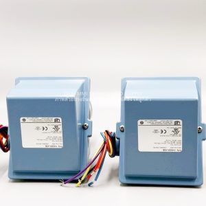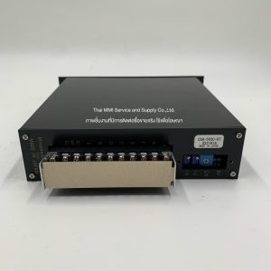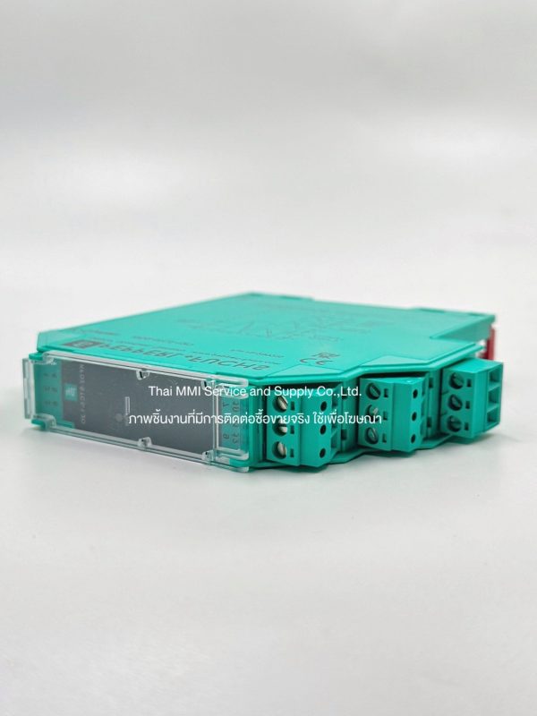


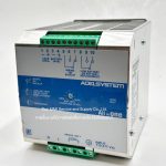
SMART Transmitter Power Supply KFD2-STC5-1.2O – PEPPERL+FUCHS
- Description
Description
SMART Transmitter Power Supply KFD2-STC5-1.2O – PEPPERL+FUCHS
- 1-channel signal conditioner
- 24 V DC supply (Power Rail)
- Input 2-wire and 3-wire SMART transmitters and 2-wire SMART current sources
- Signal splitter (1 input and 2 outputs)
- Dual output 4 mA … 20 mA current sink/current source
- Terminals with test points
- Up to SIL 2 (SC 3) acc. to IEC/EN 61508
Details: KFD2-STC5-1.2O
Function
This signal conditioner provides the galvanic isolation between field circuits and control circuits. The device supplies 2-wire and 3-wire SMART transmitters, and can also be used with 2-wire SMART current sources. It transfers the analog input signal to the control side as two isolated output signals. Digital signals may be superimposed on the input signal on the field side or on the control side and are transferred bi-directionally. The device provides a sink mode or a source mode output on the control side terminals. The device has an internal resistor. Use this resistor if the HART communication resistance in the control circuit is too low. Test sockets for the connection of HART communicators are integrated into the terminals of the device.
Technical Data
General Specifications
| Signal Type | Analog Input |
Functional safety related parameters
| Signal Integrity Level (SIL) | SIL2 |
| Systematic Capability (SC) | SC3 |
Supply
| Connection | Power Rail or Terminal 14+, 15- |
| Rated Voltage | 18 ….. 30 V DC |
| Ripple | Within the supply tolerance |
| Power Dissipation | ≤ 1 W at maximum load |
| Power Consumption | ≤ 1.7 W at maximum load |
Input
| Connection Size | Field side |
| Connection | Terminal 1+, 2-, 3 |
| Input Signal | 4 ….. 20 mA |
| Open Circuit voltage/short-circuit current | Terminal 1+, 3: 23 V / 25mA |
| Input resistance | Max. 205 Ω terminal 2-, 3, max. 330 Ω terminal 1+,3 |
| Available Voltage | ≥ 16 V at 20 mA ; ≥20 V at 4 mA, terminal 1+, 3 |
Output
| Connection Size | Control side |
| Connection | Terminal 7+, 8-, 9-; 10+, 11-, 12- (sink)
Terminal 7-, 8+, 9+; 10-, 11+, 12+ (source) |
| Load | 0 ….. 600 Ω |
| Output Signal | 4 ….. 20 mA (Overload > 25 mA ) |
| Ripple | Max. 50 µA |
| External Supply (loop) | 2 …… 30 V DC
If the external voltage is > 19 V, a load ≥ ((V-19) / 0.02 Ω is required. V represents the value of the external voltage. The internet 250 Ω resistor at terminals 9 and 12 can be used as a load. |