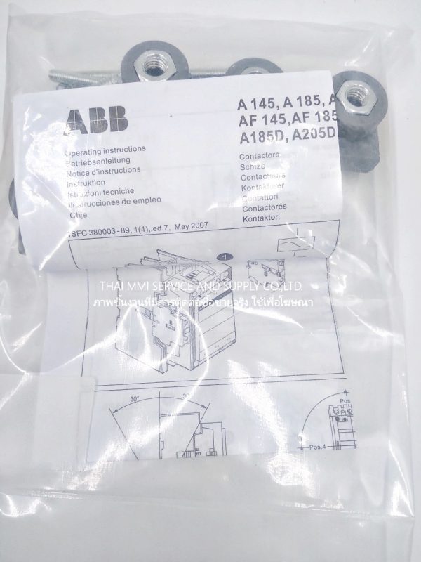
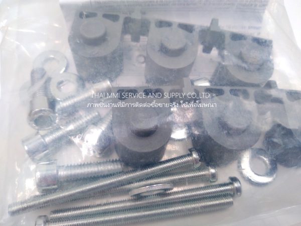


ABB – AF145-30-11 250V CONTACTOR
- Description
Description
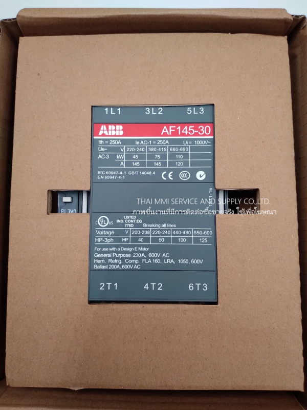
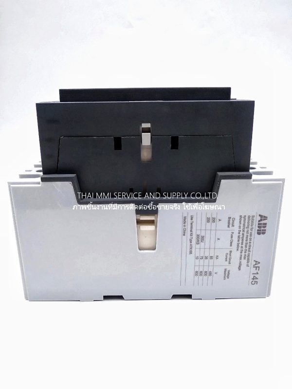
ABB – AF145-30-11 250V CONTACTOR
A 3-phase Contactor suitable for various applications such as Motor starting, Isolation, By-pass and Distribution application up to max 1000 V. Operated with wide control voltage range 100-250 V, AC/DC
Technical ABB – AF145-30-11 250V CONTACTOR
| Number of Main Contacts NO : | 3 |
| Number of Main Contacts NC : | 0 |
| Number of Auxiliary Contacts NO : | 1 |
| Number of Auxiliary Contacts NC : | 1 |
| Rated Operational Voltage : | Main Circuit 690 V |
| Rated Frequency (f) : | Main Circuit 50/60 Hz |
| Conventional Free-air Thermal Current (Ith) : | acc. to IEC 60947-4-1, Open Contactors q = 40 °C 250 A |
| Rated Operational Current AC-1 (Ie) : | (1000 V) 40 °C 180 A(1000 V) 55 °C 180 A(1000 V) 70 °C 180 A(690 V) 40 °C 250 A(690 V) 55 °C 230 A(690 V) 70 °C 180 A |
| Rated Operational Current AC-3 (Ie) : | (1000 V) 55 °C 80 A(220 / 230 / 240 V) 55 °C 145 A(380 / 400 V) 55 °C 145 A(415 V) 55 °C 145 A(440 V) 55 °C 145 A(500 V) 55 °C 145 A(690 V) 55 °C 120 A |
| Rated Operational Power AC-3 (Pe) : | (1000 V) 110 KWT(220 / 230 / 240 V) 45 KWT(380 / 400 V) 75 KWT(415 V) 75 KWT(440 V) 75 KWT(500 V) 90 KWT(690 V) 110 KWT |
| Rated Breaking Capacity AC-3 acc. to IEC 60947-4-1 : | 8 x Ie AC-3 |
| Rated Making Capacity AC-3 acc. to IEC 60947-4-1 : | 10 x Ie AC-3 |
| Short-Circuit Protective Devices : | gG Type Fuses 315 A |
| Rated Short-time Withstand Current (Icw) : | at 40 °C Ambient Temp, in Free Air, from a Cold State 10 s 1200 Aat 40 °C Ambient Temp, in Free Air, from a Cold State 15 min 280 Aat 40 °C Ambient Temp, in Free Air, from a Cold State 1 min 600 Aat 40 °C Ambient Temp, in Free Air, from a Cold State 1 s 1800 Aat 40 °C Ambient Temp, in Free Air, from a Cold State 30 s 800 A |
| Maximum Breaking Capacity : | cos phi=0.45 (cos phi=0.35 for Ie > 100 A) at 440 V 1500 Acos phi=0.45 (cos phi=0.35 for Ie > 100 A) at 690 V 1200 A |
| Maximum Electrical Switching Frequency : | AC-1 300 cycles per hourAC-2 / AC-4 150 cycles per hourAC-3 300 cycles per hour |
| Rated Operational Current DC-1 (Ie) : | (110 V) 2 Poles in Series, 40 °C 250 A(220 V) 3 Poles in Series, 40 °C 250 A |
| Rated Operational Current DC-3 (Ie) : | (110 V) 2 Poles in Series, 40 °C 250 A(220 V) 3 Poles in Series, 40 °C 250 A |
| Rated Operational Current DC-5 (Ie) : | (110 V) 2 Poles in Series, 40 °C 250 A(220 V) 3 Poles in Series, 40 °C 250 A |
| Rated Insulation Voltage (Ui) : | acc. to UL/CSA 600 Vacc. to IEC 60947-4-1 and VDE 0110 (Gr. C) 1000 V |
| Rated Impulse Withstand Voltage (Uimp) : | Main Circuit 8 kV |
| Mechanical Durability : | 5 million |
| Maximum Mechanical Switching Frequency : | 300 cycles per hour |
| Coil Operating Limits : | (acc. to IEC 60947-4-1) 0.85 x Uc Min. … 1.1 x Uc Max. (at θ ≤ 70 °C) |
| Rated Control Circuit Voltage (Uc) : | 50 Hz 100 … 250 V60 Hz 100 … 250 VDC Operation 100 … 250 V |
| Coil Consumption : | Holding at Max. Rated Control Circuit Voltage 50 Hz 12 V·AHolding at Max. Rated Control Circuit Voltage 60 Hz 12 V·AHolding at Max. Rated Control Circuit Voltage DC 2 WPull-in at Max. Rated Control Circuit Voltage 50 Hz 430 V·APull-in at Max. Rated Control Circuit Voltage 60 Hz 430 V·APull-in at Max. Rated Control Circuit Voltage DC 500 W |
| Operate Time : | Between Coil De-energization and NC Contact Closing 40 …. 50 msBetween Coil De-energization and NO Contact Opening 43 … 53 msBetween Coil Energization and NC Contact Opening 45 … 85 msBetween Coil Energization and NO Contact Closing 50 … 90 ms |
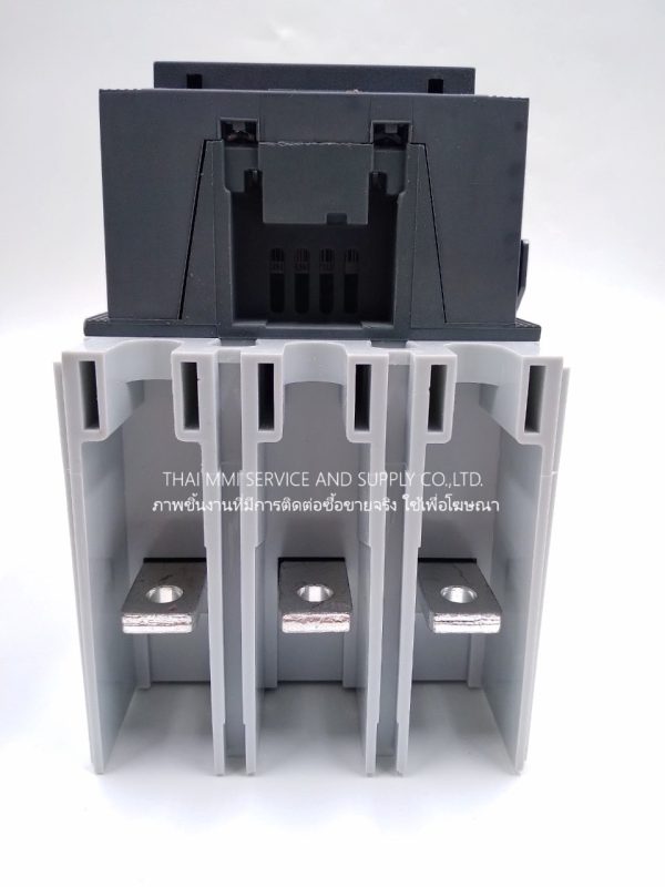
| Connecting Capacity Main Circuit : | Bar 24 mmRigid Al-Cable 1 x 25 … 150 m²Rigid Cu-Cable 1 x 6 … 185 m² |
| Connecting Capacity Auxiliary Circuit : | Flexible with Ferrule 2x 0.75 … 2.5Flexible with Insulated Ferrule 1x 0.75 … 2.5Flexible 2×0.75 … 2.5 m²Solid 2 x 1 … 4 m²Stranded 2 x 1 …. 4 m² |
| Degree of Protection : | acc. to IEC 60529, IEC 60947-1, EN 60529 Coil Terminals IP20acc. to IEC 60529, IEC 60947-1, EN 60529 Main Terminals IP00 |
| Terminal Type : | Main Circuit: Bars |